Axial (Sliding Armature) Starter Motor
The main features of this type starter motor are its size and robust construction. For the engagement of the pinion to the flywheel ring gear, the complete armature assembly slides axially through the motor casing. A simplified construction of the starter is illustrated in Fig. 15.27. In the figure, the motor is shown in the rest position. The armature is held by a spring so that it is offset to the field poles. When the field is energized, the armature is pulled to the left and the pinion is slid into engagement with the ring gear.
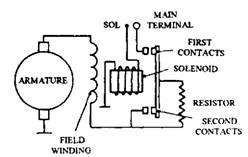
Figure illustrates the electrical circuit of the starter motor, which uses three field windings. The main winding as usual is of thick-section and low-resistance winding, and is connected in series to the armature. The auxiliary winding is wound with thinner wire so that it has a relatively high resistance, and is also connected in series with the armature but in parallel with the main winding. The holding winding is also a high-resistance winding but is connected in parallel with the armature as well as with the other two windings.
A two-stage solenoid switch, mounted on the starter operates the Delco Remy starter, and is energized by the driver’s

Fig. 15.28. Circuit of axial motor.
^switch. When the switch is operated, the first pair of contacts closes but the second pair is held open by a pawl that engages in a slot in the trip lever. Once the pinion is near fully engaged with the ring gear, the pawl allows the second pair of contacts to close.
Figure 15.29 illustrates the operation of the motor. Figure 15.30A shows the first pair of contacts is closed, which energizes the auxiliary windings, holding windings and armature. The armature rotates slowly and moves axially so that it is central to the field poles. Simultaneously,
the pinion is slowly slid into mesh with the ring gear. When the pinion is on the verse of its full engagement, the release disc on the armature strikes the pawl so that the trip lever closes the second pair of contacts (Fig. 15.29B). Now current passes through the main windings, causing the motor to develop its full torque.

Fig 15-29. Action of axial motor. A. Closure of first contacts. B. Closure of second contacts.
As cranking speed rises, the current through the main and auxiliary windings decreases due to back emf generated by the rotating armature, especially when engine fires spasmodically but does not actually start. Now the magnetic strength in the main and auxiliary winding is insufficient to oppose the armature return spring and hold the pinion in full engagement. However, this is prevented by the holding winding as the current in this winding is not affected by the back-emf. Once the pinion has de-meshed and the armature has returned back, the momentum of the rotating mass tends to keep the armature rotating. This is however resisted by the ‘generator effect’ developed due to the interaction of the holding winding and the armature. This electrical reaction quickly brings the armature to rest. The pinion joins to the armature shaft through a small multi-plate clutch, which serves two functions.
(i) It slips when the torque applied to it exceeds a predetermined limiting value, so that the starter is safeguarded from damage if the engine backfires.
(ii) It disengages when the engine starts and tends to drive the pinion faster than the armature, so that the armature is prevented from damage by excessive speed.

Fig. 15.30. Circuit diagram of coaxial starter.
Tips from:http://what-when-how.com